There’s More To Modeling Miniature Railroads Than Just the Model Trains and Tracks
Like most of us, your passion miniature scale model trains was probably ignited by a first encounter with a model railroading magazine such as Model Railroader, or Model Railroad Hobbyist. In due course, you probably obtained a boxed starter set with a locomotive, several cars, and an oval of track.
After about the third circuit of your new train around the new oval, you are thinking of other destinations for the rolling stock, and out comes the catalog or the web page to order…turnouts and more track!
© Copyright http://www.modelbuildings.org All rights reserved.
Now you have a problem, because there are LOT of choices for track. Nowadays, many starter sets come with track that includes plastic roadbed into which the rails are set. This is fine for the casual under the bed or under the Christmas tree temporary layout. But you’ve REALLY been bitten by the model railroading bug and you are looking ahead to having a totally realistic model pike. The magazine articles usually feature finely constructed layouts which have evolved over many years and thousands of hours, and virtually none of them are based on rail trackage that includes embedded plastic roadbed and ballast. In fact, thousands of words have been written about various techniques to make your track appear as realistic as possible. None of them mention plastic roadbed!
Prototypical switches are constructed to fit a particular use and location. There are certain minimum requirements that are met, but generally they are engineered to standards and according to the scenery, terrain and nature of the traffic they will carry. As modelers, we have the restriction of mass production, which dictates that we have to use one or more of standardized turnout arrangements that can be profitably reproduced by the thousands.
To appreciate how the switch actually functions, we need to have a close look at the rolling stock wheels and how they interact with the rails.
The train wheels are equipped with a flange, which serves to keep the wheel aligned with the track, but more importantly, and less visible, is the geometry of the wheel itself. It has a very slight cone shape, and for a very good reason. If the wheel were simply a section of a cylinder, it would be free to rotate and turn in any direction if acted on by an outside force. A cone, however, will inscribe a circle about the narrow end of the cone if it rolls. By joining two conic sections at their base with an axle, a wheelset is created that will always attempt to run straight and true naturally, with the opposing cone rotations cancelling the tendency to turn.
Generally, this is enough to keep the structure which contains the wheels, the truck, running straight. However, in some situations, the wheels need an additional feature to keep them on the track. A flange is used at the inner edge of the wheel which prevents it from riding off the rail at that time. The rail itself helps the process by having a flat top with somewhat rounded edges to match the conic section.
The ingenious net result of these designs is a situation in which a simple mechanism can be created that allows a multithousand ton freight train to gracefully move from one route to another.
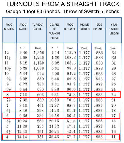
Track turnouts are given numerical designations to describe the angle at which the rails cross the frog of the switch (see above illustration). This, in turn determines the “closure radius” of the turnout.
Higher numbers indicate larger radii through the turnout diverging route. The National Model Railroad Association publishes recommended practices for the construction of model turnouts for #’s 4 through 20 in section 12. NMRA Standards and Recommended Practices can be found on the web The data in section 12 is extremely detailed and can be difficult to read. However, the data can be generalized as follows:
1. Larger numbers indicate smaller frog angle, thus larger closure radius.
2. As the closure radius increases (larger turnout number) the length of the lead rails increases.
3. As the closure radius increases, the length of the switch rails increases
4. As the closure radius increases, the length of the frog increases.
In short, larger numbered turnouts require a lot more space. If you are building a small train layout, you may be thinking of using #4 turnouts throughout your design. This is fine if you are also planning short trains, low speeds, and short wheelbase rolling stock. However, if you shouldn’t plan on successful or satisfying operation of Challenger or Big Boy class locomotives and very long passenger and freight cars through #4 turnouts! Operational success isn’t the only challenge, either. We all want our railroads to look as real as possible, but trying to cram large equipment through tight turnouts looks very unrealistic! You will also soon tire of dealing with frequent derailments.

Model equipment manufacturers typically supply turnouts in #4, #6, or #8 size. Larger frog numbers may be available from some suppliers, but most distributors stock these common sizes. Some manufacturers do not label their turnouts with numerical designations, but quote a “radius” figure that matches their common curved sectional track radii. You might have to do a little research with the manufacturer and some calculations or actual measurement if you need to know what the actual frog number might be.
REALLY Modeling It
Very serious modelers often hand lay their own rail. If you are seeking the ultimate in realism, you might consider this technique, but it would be advisable to experiment with a section of rail OFF your layout before taking the plunge. If you are going to hand lay rail, you will probably want to hand lay your turnouts as well. Hand laid rail requires some specialized tools and a LOT of patience. There’s no disputing that well done hand laid model track can be indistinguishable from the real thing. Some would also say that hand laying your own rail and laying actual prototype track involve about the same effort!
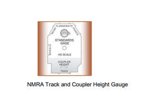
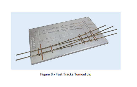
Two important tools you will need to do this job are an NMRA track gauge and turnout jig tools for the size and arrangement of turnouts you plan to build. Look at the turnout sketch above and remember that there are a lot of little pieces that make a turnout. Jigs keep you sane by holding everything in place until you can drive the spikes into the ties to secure the rails properly. The company called Fast Tracks has a complete system of rail laying products which have a very good reputation in the modeling community.
One word of caution. If you are planning to save money by doing track work by hand, disabuse yourself of the notion IMMEDIATELY! Consider that you need to buy a lot of special (expensive) tooling, and that the raw materials aren’t really any cheaper than an equivalent item pre-made. That’s powerful incentive to approach the concept of building your own with interest – but not involvement!
If you are determined to seek that next level of realism, you might want to first try building a module using hand laid techniques. N-Track or One-Track or Free-Mo modules can be simple and good practice, and you can get an idea of just how much effort and expense is going to be involved before you jump in with both feet
The Turnout in Use
What are you using your turnout for? Does it lead to a dead-end siding? A mainline passing siding? A yard ladder? Each of these uses have slightly differing requirements. As mentioned above, low frog number turnouts aren’t conducive to long and fast train operations, so #4 or #6 turnouts might be just fine for a stub siding or a ladder for a small classification yard. For mainline passing sidings, you will want a range of speed and train capability, so #8 or even larger frog numbers might make more sense. You won’t be doing switching movements with an SD-90 or E8 or Mikado, but you will be doing passing movements that require a lot of clearance and some relatively higher speed.
Clearance is also an issue. Turnouts which have above-the-layout switch machines need to be arranged so that the locomotive overhang will not conflict with placement of the switch machine.
This is particularly important when building yard ladders, where rolling stock of different lengths will traverse the turnout. Turnouts operated from beneath have no such restriction, but you’ll need to consider placement of the switch machine relative to any benchwork limitations under the layout. Maintenance under the layout is much less convenient than on top, so try to minimize the impact of placement.