Controls and DCC – A Model Railroaders Dreams Of Realism Come True!
Before the arrival of DCC systems, large model railroad layouts often needed long runs of wire to control remote turnouts from a central control panel. Such a large commitment to point-to-point wiring is not only expensive, it is difficult to maintain and exceptionally hard to modify. Any change to track and turnout configuration often required the removal and replacement of many meters of wire and a lot of time to complete. Such a system is also prone to wiring errors and damage when modifications arise.
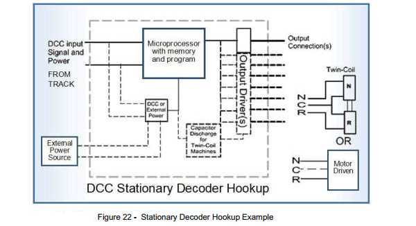
Only power is required at the turnout location on a DCC layout. Control signaling is done via DCC packet over the rails to a co-located stationary decoder that may be operated right from the engineer’s DCC throttle. Let’s take a closer look at how DCC control of stationary turnout decoders works.
© Copyright http://www.modelbuildings.org All rights reserved.

Digital Command Control (DCC)
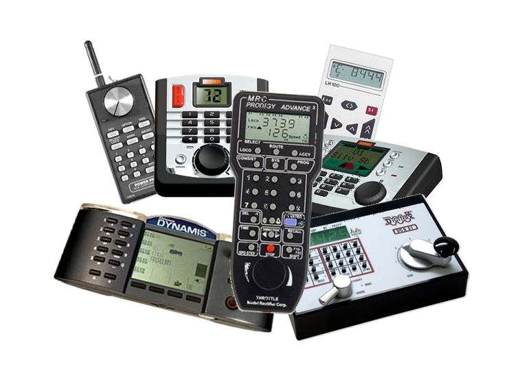
We won’t go into a detailed explanation of how DCC works, there are many books and articles that explain the operation down to the last bit. At the highest level, DCC is simply a method by which uses a handheld control unit to tell a computer (the command station) to send instructions to another small computer (the decoder). If you look at each of the above pieces carefully, you can see that this is exactly the same architecture used in video game consoles. The command station is the same as the game unit, the decoder part is played by the video display (television or monitor), and the handheld control unit is like the game controller.
Let’s extend the analogy just a little further. If you visualize having a game system console with several monitors, each displaying a different game and responding to different controller inputs, you have the complete picture. The only real difference between DCC and your Xbox is that instead of a monitor playing complex graphics, the decoders perform a very limited set of electrical operations.
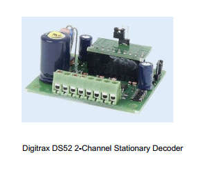
The DCC Decoder
In the previous analogy, we had a console using multiple displays, each running a different game. How would the wiring for this system look? It would probably take the form of an HDMI cable from the game console to each individual monitor. If you wanted to have a lot of games playing at the same time, the wiring starts to become a problem. A great way to solve that would be for all the monitors to only need a wall power outlet and NO wires to make the display work. Wait…where have we seen that kind of thing before?…Oh yeah! A computer network – like the Internet – works that way!
Getting all the pieces to work together on a network (DCC or the Internet) leads us to the notion of addressing. Once again, let’s use an analogy.
If someone sends you a letter via the post, it will usually come in an envelope. On the face of the envelope is written the location, or address, of a place where you regularly check for like items that are delivered by your postal service. Computer networks (and DCC) are very similar.
Every device attached to the network (the rails), in our case decoders, has a unique electronic address that distinguishes it from every other device on the network. When you buy or build a decoder that is new on your DCC network, you have to configure it for certain actions. This is called programming, and during the setup you will assign your new decoder an address that isn’t in use by some other decoder on your DCC system. There are other things that you may configure, but for the moment, the address is the important setting.
The Network
Early computer network technology operated on pairs of wires that were actually physically connected from one computer to another. We’ve since mostly adopted wireless technology for our Internet access, but DCC still uses that physical connection concept. Where the computer network used wire pairs, DCC signals are carried from the command station to the decoders by the rails. As we all know, the rails also carry the power to operate the locomotive motors, so DCC makes changes to the track power in a certain standardized manner that is called out in a document published by the National Model Railroad Association (NMRA). Although NMRA is based in the USA, DCC systems world-wide adhere to it. Doing so allows a manufacturer to insure that its equipment will operate correctly with every other manufacturer’s equipment at some basic level. There is room in the standard for special features that a manufacturer might want to include, but a basic identical feature set must be accommodated.
DCC Command Station
Each DCC network has a command station. The purpose of the command station is to interpret what the engineer wants to do from the signals the command station gets from the walk around throttle units. If an engineer wishes to line a turnout, a sequence of button presses on the handheld throttle will tell the command station which turnout and what route to assume. The command station translates this into an address, to which it adds the instruction to do the action, and then puts a signal on the tracks. The command signal is “heard” throughout the network by all the decoders, and the one to which it is addressed will perform whatever function is requested. In the case of a turnout stationary decoder, it will send a signal to the turnout motor or solenoid to line the turnout either straight through or diverging.