Understanding How Model Railroad Current Functions – DC and DCC
Let’s do a short introduction to the theory before we really dive deep into it. Model railroads today are powered in two different ways. The motors that the locomotives use are either powered by alternating current (AC) or direct current (DC). The fundamental difference is that while DC voltage maintains a constant value over all time (assuming the throttle is left alone), while AC voltage oscillates back and forth between somepositive voltage and an equal, but opposite polarity, negative voltage. © Copyright http://www.modelbuildings.org All rights reserved.
Model Train Current Flow
Generally, you will find that O-scale and S-scale trains by Lionel, MTH, American Flyer, and some other manufacturers are AC powered. The larger sizes by Lionel, MTH, and others are nominally “O-scale” are generally referred to as Hi-Rail and are recognizable by the third center rail on the track, which is used as the common point for the current return. American Flyer uses two rail track, but the operation of the trains is similar. Each locomotive has a solenoid that is used to ‘shift’ the locomotive from forward to reverse. Since the current flows in both directions, the current flow reversal can’t be used as a way to make the motor run backwards. The use of AC current on these trains makes the use of strictly defined DCC inconvenient. This is not to say that individual locomotive control can’t be done on Hi-Rail Layouts. Lionel and MTH both have systems that can control addressable locomotives, but not being DCC, they won’t be covered here. Recommended resource http://www.dccmodeltrains.org
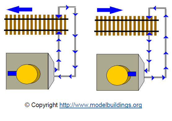
Z, N, HO, OO, some O, and G scale locomotives for the most part use DC current and are able to reverse the locomotive direction by using a switch on the power supply to reverse the direction of the current flow on the rails like pictured here.
It is this continuous flow of current in one direction that makes DCC a good fit for your layout. In fact, DCC impresses a communication signal on the direct current on the rails that sends information to a control unit in the locomotive or other model device.

DCC Trains – How They Operate
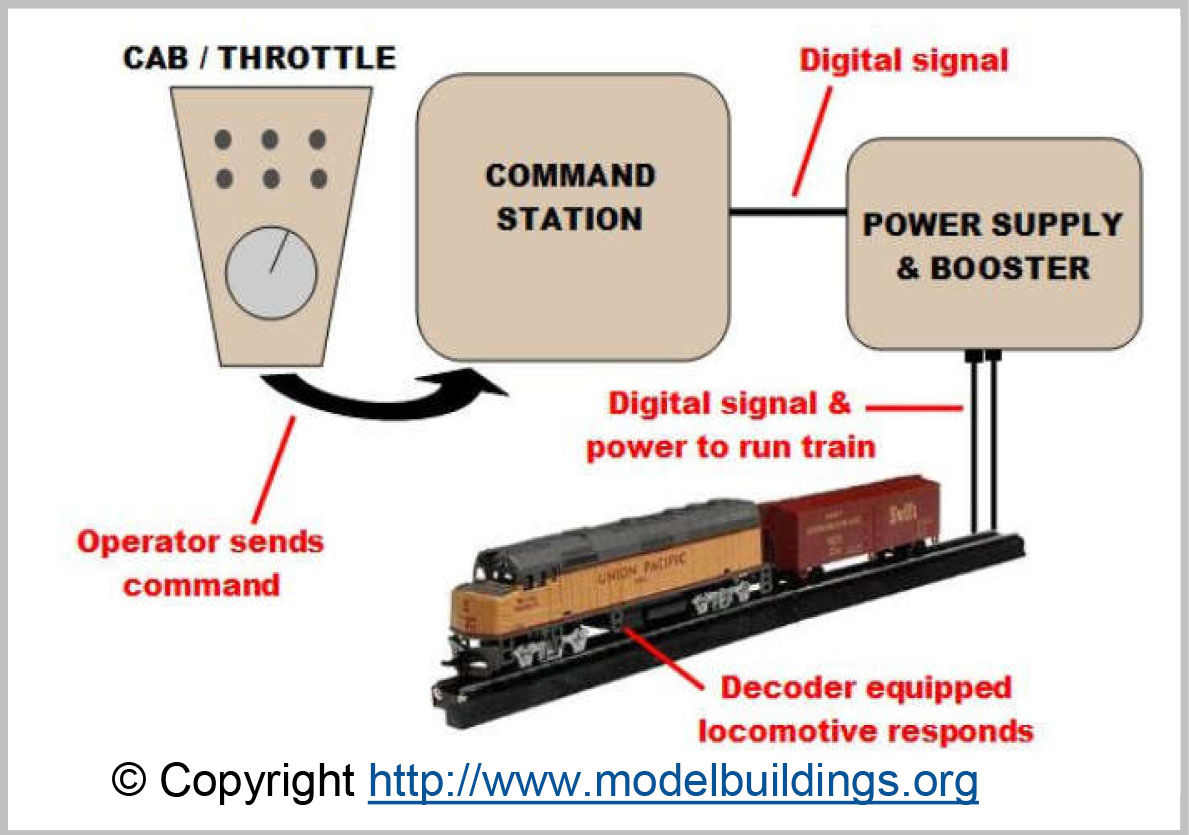
We have to step back and take a look at DCC as a whole system first. In the highest level terms, there are three basic components to a DCC system. Each system consists of a command station, a power supply, and a decoder. All the units are essentially connected together. The power supply and command station are wired together (why they are, we’ll discuss shortly), and the command station is connected to the decoder through the track. Why should this be so?
Well, the command station is having a conversation with the decoder, so it’s pretty important that the decoder has a good connection to the command station, and what better electrical conductor can we have than the track? What? Wireless, you say? Well, yes, there are non- DCC control systems that use wireless means to communicate with the decoder, but we’re not going to talk about those here. The only other alternative we’d have to the track connection is to drag pairs of wires behind the locomotive everywhere it goes. That’s pretty silly, so it makes the most sense to use the track for the connection which we’re going to call the data link.

A data link is simply a connection between two communicating devices, in this case the command station and the decoder. Now, it might be tempting to think of the data link as a physical attachment of some kind, and in this case it is, but what is more useful for our purpose of DCC (and all other types of communication as well), is that there is a data link relationship in the information that travels across that connection. When the decoder recognizes data sent to it by the command station, a logical data link exists between them.
In order to work correctly, the data that the decoder thinks it is getting from the command station must be the same as the data that the command station is actually sending. Obviously, it’s very important that whatever is between the command station and the decoder not cause any corruption of the data. That means that the quality of the link between the command station and decoder is highly dependent on the condition of the track and the electrical pickups on the wheels. In this respect, both DCC and DC controls have the same requirements. Clean tracks and good electrical connections make for good operation.
A data link doesn’t just come into being by itself. The simplest form of data link in communications theory is a point-to-point system in which there is no ambiguity about the source or destination of the information exchange. In DC (also called analog) control, this very situation exists. When some information is sent from the power pack – the information in this case happens to be the voltage – the unmistakable destination is the single locomotive on that segment of track. This particular example is the most simplistic in content as well, as there is really only one bit of information, the voltage, being sent across the data link. Since we are trying to do something a lot more sophisticated with our trains, we need to have something with a little more capability.
In order to do this, we need some mechanism by which to send two pieces of information to whatever it is we want to control. First, we need to send a message that identifies just what we want to have happen, and then we need to send a message saying how much should happen. For example, if we want to turn on a locomotive headlight we need to say, “turn on the headlight”. Then we need to say, “Set the headlight to half brilliance.” That’s impossible to do when all we have is a knob that controls the track voltage.
But suppose we think a bit and come up with an idea that if we send the full track voltage for a few seconds, then turn the knob back and send half the track voltage for a few more seconds, we can somehow represent that half-headlight condition. We have just discovered the concept of a remote control system. Naturally, DCC is much more complex than that. However, the same principle applies to virtually any control system in existence today.
Operating Model Trains With Electronics and Circuitry
In the early days of electronics, there were many control systems that operated by the transmission and sensing of different levels of voltage or different frequencies of tone sent on the data link (which is commonly called a control link). These systems operated well when there was a clearly discernible difference between the control states. However, the nature of all transmission is that there is some loss of fidelity over long distances because the signal tends to become weaker and get lost in noise. The remote end of the link will start to make mistakes because what it sees as a command has in some way become corrupted by the noise of the intermediate transmission medium. Compensation was done with amplifier units between the transmitter and receiver, which increased the signal back up to a usable level. However, the amplifier not only increases the signal, it also increases the noise, so at some point it becomes useless to add more amplifiers. Moreover, the hardware to recognize the different levels of signal becomes very complex very quickly. An analog circuit is typically capable of only identifying one value of interest, so for complex actions the circuitry gets huge and difficult to make portable.


