
Essential Electrical Work On Model Railroads – Where To Start
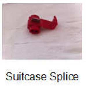
While you are working on your track joining soldering technique, you should also take the time to practice attaching power feeder wires to the track. Even with a small layout, electrical distribution is an important point. The farther a locomotive is from the source of the voltage, the less voltage is available to power it because of the resistance of the rails. In order to overcome this, feeding power to a larger size wire bus under the layout and tapping off smaller feeder wires with suitcase splices to various sections of the layout is much better than a single connection close to the power pack. Pair of #12 or #14 wires carries the primary current from one end to the other, and #18 or #20 feeders make short runs to the track, where they are soldered in place to the rails. This provides a full voltage source to any point on the layout. © Copyright http://www.modelbuildings.org All rights reserved.
A Guide To Soldering Feeder Wires
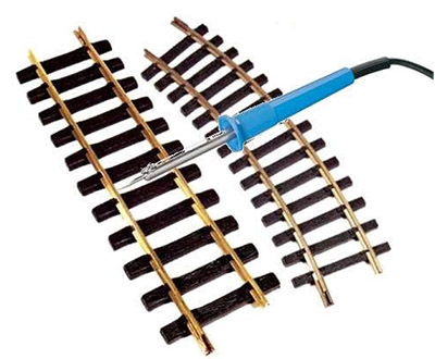
To solder feeder wires to the track, strip off about ¼” of insulation and tin the bare wire. Bend the bare end into an “L” shape and lay it alongside the outside rail edge. Apply paste or liquid flux to the joint and apply heat, then solder to the joint. The solder should flow freely over the wire and the rail. When soldering, be sure to use paste or liquid flux on every connection. This cleans the connection and promotes the flow of solder through all the joints. Also, clean each joint with a fine grit sandpaper or your Bright Boy track cleaner to remove surface dirt. Make sure the iron or soldering gun is well tinned, and use enough heat to make sure the solder flows. It should wick into the joint and not ball up on the surface. To keep from melting the plastic ties, you can use a water soaked cotton ball or a small hemostat clamp on each side of the joint to draw the heat away. When you have finished the joint, run a fingernail over the top of the rail to make sure the joint is smooth and level (no bumps over the joint), and check that no solder has gotten to the inside of the rail to impede the wheelset flanges. If necessary, use a small hobby file to smooth everything out.

Operating Multiple Trains
Multiple train operation needs special electrical attention. Rather than have one large bus that distributes the same power to all portions of the layout, one of two systems will be used. Historically, if you wanted to run multiple trains, you divided the layout into “blocks”. Each block is created by using insulated track join-ers to isolate the section of track, and the locomotive voltage to each block is controlled by an on-off switch which will allow the movement of the train only within that block. Each block will have a throttle control or use a switched throttle to control the train in that block.
Block control wiring gets complicated very quickly, and any track changes to the layout are likely to involve major rearrangements of the electrical feeds. Electronic microchip and computer technology has given us Digital Command and Control, DCC, which overcomes all of that difficulty.
DCC, Decoders, and Power Districts Explained
A DCC layout will have the constant maximum voltage applied to the rails all over the layout at all times. A command transmitter places control signals on the track, which are received and interpreted by a small circuit called a decoder in the locomotive. The decoder controls the amount of voltage going to the loco-motive motor. Each locomotive has a unique address that the command station will use to control that lo-comotive independently of any other. The decoder may also control other functions such as special loco-motive lights and sound effects, and decoders can also be used with fixed accessories and with turnout motors for control of nearly every aspect of movement on the layout.
Although the initial entry price for DCC is higher than for a standard analog control power pack, the initial investment is well worth it the minute you start thinking about more than one train. Also, keep in mind that the encoder is not powering the train, so you’ll still need a power pack or source of DC voltage and current appropriate to the locomotives.
Some DCC systems use the concept of “power districts”, where multiple power supplies or multiple fused circuits are used for the distribution of the track power. Rather than control, the purpose of the power dis-tricts is to level the load and protect the DC power supply in case of shorts caused by derailment or other issues.
Current Capacity, Switch Machines, Crossing Signals, and Accessories
If you are planning to use electric switch machines or “snap” switches, you’ll need to run wiring to operate them as well. Switch machines, block signaling, operating crossing signals, and building interior and exte-rior lighting are all operated from the accessory terminals of the power pack, or from auxiliary power sup-plies of the correct voltage. Each accessory draws a certain amount of current under load, so be sure to add up all the requirements and not exceed the capacity of the power supply in use. Doing so will cause unreliable operation of the accessories and causes overheating and the possibility of fire. Also, when powering your accessories, research the current carrying capacity of the wire gauge you are using and use a larger size if you are close to the capacity.
Figuring out the current is easy; you simply add together all the current loads of all the devices on the cir-cuit and size everything to handle that with a comfortable excess margin. A Google search will lead to a chart that shows current carrying capacity for any size wire.