The Important Role of Switching
when Turning the Train
A “switch” or “turnout” (“turnout” is a model railroading term. In prototype railroads, it’s always a “switch”) is a special piece of track that allows rolling stock to be guided to an alternate track path. In order to do this, some special features are constructed that guide the train wheels around a movable set of special rails and onto a diverging route.
Although the operation of a railroad switch might seem simple, it is successful because of a long history of careful design and implementation to improve the movement of rolling stock around the rail network. Safety has played an important part in the development as well.
© Copyright http://www.modelbuildings.org All rights reserved.
Train and Rail Components
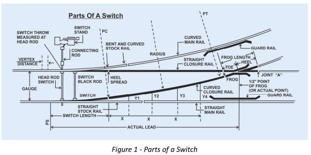
A switch has a number of different segments of rail that allow the operation. There are two stock rails, two main rails, two closure rails, two guard rails, two points, and one element called a “frog”. There is also a connecting rod that causes the points to move in response to a lever throw or an electric motor drive.
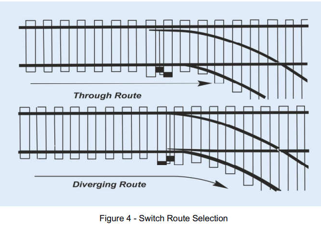
Switches may differ somewhat in their physical arrangement, but all will have moveable rails, called the switch points, which affect the guide of the wheelsets. They start with a tapered section in contact with either the inside or outside main rail, depending on whether the switch is lined to the through route or the diverging route. At the other end of each point rail is a pivot point about which the rails are free to move.
To appreciate how the switch actually functions, we need to have a close look at the rolling stock wheels and how they interact with the rails.
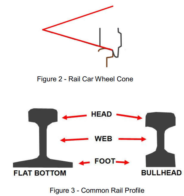
The train wheels are equipped with a flange, which serves to keep the wheel aligned with the track, but more importantly, and less visible, is the geometry of the wheel itself. It has a very slight cone shape, and for a very good reason. If the wheel were simply a section of a cylinder, it would be free to rotate and turn in any direction if acted on by an outside force. A cone, however, will inscribe a circle about the narrow end of the cone if it rolls. By joining two conic sections at their base with an axle, a wheelset is created that will always attempt to run straight and true naturally, with the opposing cone rotations cancelling the tendency to turn.
Generally, this is enough to keep the structure which contains the wheels, the truck, running straight. However, in some situations, the wheels need an additional feature to keep them on the track. A flange is used at the inner edge of the wheel which prevents it from riding off the rail at that time. The rail itself helps the process by having a flat top with somewhat rounded edges to match the conic section.
The ingenious net result of these designs is a situation in which a simple mechanism can be created that allows a multithousand ton freight train to gracefully move from one route to another.
How the Railroad Switch Works
The tapered moving point rails are the initiator of the switching process. Either the inside or the outside rail will be in contact with the mainline rails, depending on how the switch is lined. For straight through operation, the point rail and mainline (or “stock”) rail which are parallel to the straight through route will be held together by the switch rod. This arrangement guides the wheelset in a straight line along the closure rail that also parallels the straight-through route.
Finally, the wheelset remains aligned on the straight-through route in the frog, and continuing ahead to through out of the switch.
If the switch rod is holding the non-parallel route point rail against the stock rail, the wheel will be guided off the main line and into the diverging route. The wheelset moves over the opposite side closure rail, now aligned in the direction of the diverging route. The wheelset moves through the frog with the wheel tracking on the other side of the frog rails, and finally out of the switch on diverging route.
Efficient Train Operations Vital On Any Railroad (full size or scale model)
In locations where only the occasional local freight train is switched, it is common for the points to be moved by a manual lever. The engineer will stop the train prior to the switch, then the brakeman or trainman will walk to the switch stand and throw the manual lever to line the switch in the desired direction.
Once this is done, the engineer will slowly move the train completely through the switch and the trainman will replace it to its default position.
Large yard and mainline operation is usually accomplished with a motorized switch operated by a control and dispatch center. In the early days of centralized traffic control, or CTC, a large board with many electromechanical switches was used to route trains remotely. Each individual electrical selector would control one or more switches, each move managed by the dispatcher.
Nowadays, the control and dispatch centers look like NASA control rooms filled with computer screens and operated by professional dispatchers who are always in touch with the train crews by two-way radio. Trains are tracked with GPS and can be pinpointed to within a few feet of their locations. Sophisticated computer software make the management of huge rail networks much easier than in earlier times. The computers issue commands to the electronics that control the switch motors so that there is no need for personnel to leave a train in order to line switches. In fact, most modern railroad trains only have two on-board personnel – the engineer and the conductor.